I have successfully finished yet another garage-shop electronics project that actually WORKS!
Tuesday, Pastor Mike at Rez announced that in two weeks, when they’re on their short-term missions trip to India, they’ll be performing yet another Skype call in to 6:33 pm. However, the last two or three times they’ve been anywhere, they’ve tried this, and every time it’s been a rig. Here’s how they did it: a laptop on their end runs Skype, the Mac computer on our end runs Skype, but the bandwidth is low enough that we can only manage video. The audio cuts in and out. So for audio, we do a regular cellphone call (and use the headphone jack on the phone to pipe it into the sound board at church). And on top of that, we relied on the built-in mic in the cell phone to pick up any audio for the overseas guys to hear. A really poor setup to say the least. And each time, I’ve promised to come up with a better solution for next time.
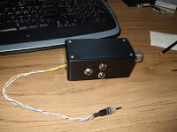
Well, I finally did. After 3+ skype calls, I finally broke down and built a phone to generic audio converter box. This basically takes the standard 4-conductor headphone jack that plugs into any modern phone for hands-free devices, and converts all three circuits into ¼” monoral TRS jacks. These jacks are left and right headphone audio out, and microphone in.
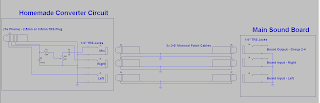
It took a little more than just straight wires on the microphone, simply because the output from nearly any audio device (except for a real microphone) are going to be a lower impedance than the input on the cell phone can handle, so I had to dumb it down with resistors. With some help from my dad making a few modifications to my schematic, I was able to solder and wire everything up yesterday, and then just an hour ago, I managed to find a workable solution to hook it up to my computer at home and make it all work. And yes, it did work! I called my mom on her phone while the box was plugged into mine, and I was able to speak into a big microphone and she heard me, and then I hooked the audio out to my computer and I was able to hear (and even record) her over my computer speakers. YES!!
One of my biggest goals for this particular project was making sure that all the connections were well insulated and well soldered in. I have made several projects that had pretty poor solder joints and were always giving out. I didn’t want that to happen this time. So I made sure that all of my leads were long enough and that there were no nicks in any of the wires. It seems to be solid! Everything works beautifully and there are no shorts anywhere.
My BIGGEST problem was soldering up the 4-conductor surface mount headphone jack. This was one type of thing I could not for the life of me find instructions on how to do. Nor was I expecting it to be that difficult. But the device was I think ROHS-compliant and thus did not take regular solder all that well. Besides that, I didn’t have a fine-tip solder iron, nor any fine-pitch solder. I don’t have the money for a $400+ Weller. All I have is a 40 watt radio shack iron.
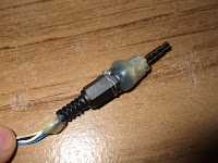
Well the solution I came up with was to just completely remove the plastic insulation from around the four conductors on the headphone jack and then just wrap around the single-strand cat5 wire around each of them and solder them into place. Once hot enough, the solder flowed fairly well and I didn’t have any big problems after that.
Actually I did have one minor problem, but that’s when I fell in love with hot glue. After soldering up those wires to the 4-conductor headphone plug, I found that I needed to insulate them from one another. But I didn’t have any 1/8″ heat shrink, so I decided to use what I saw one tutorial on the web use: hot glue! With a toothpick I was able to get a little glob of melted glue down between all of the leads on the headphone jack. But then the ground tab didn’t want to bend back in all the way (and make room for the black plastic housing), so I just pushed the housing as far on as it would go and then glued that in place as well.
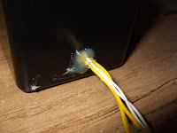
On top of using hot glue to pretty much epoxy the entire plug assembly shut, I also used it to stress-relieve the hole in the box where the wires for the plug were coming through. Since I used a drill to come through the main plastic project box, there were rough edges which would eventually have worn through the insulation on the wires. No longer. They’re glued in!
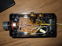
Lastly, I used perfboard to wire in the microphone volume control and other impedance-matching components including a 1uF capacitor to remove DC offset on the line. Works great! The potentiometer I drilled into the side of the box opposite the headphone plug. Then on an adjacent side, I drilled in the three ¼” TRS jacks, 2 for audio out, 1 for audio in.
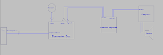
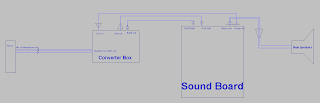
With all of this in place, I will be able to take three patch cables and connect them between my box and an audio input and output on the sound board. Since the group is going to do their thing in TWO weeks, I’ll be able to go in next Tuesday and do a test run with Dad. I’ll hook up either his phone or my phone and we’ll test it out with the other in the other room/other end of the building. The goal will be to communicate with the remote phone via the large speakers and a hand-held mic, both of which feed into the big sound board.
Is this how they do it on radio with making calls in? Sure. But some company has probably made this sort of thing a lot cleaner and flawless. However, I made it myself and it works! And it only cost me $20. Well…besides the box, which I already had from another project years ago. But yes! It works!! And if I can get my own patch cables at home, I’ll be able to record YOU when YOU call me! Or maybe phone interviews or anything else! So excited that this actually works. HA!
Leave a Reply